Post
RPI - GPIO Example
Python (RPi.GPIO) API
We’ll use the RPi.GPIO module as the driving force behind our Python examples. This set of Python files and source is included with Raspbian, so assuming you’re running that most popular Linux distribution, you don’t need to download anything to get started.
On this page we’ll provide an overview of the basic function calls you can make using this module.
Setup Stuff
In order to us RPi.GPIO throughout the rest of your Python script, you need to put this statement at the top of your file:
import RPi.GPIO as GPIO
That statement “includes” the RPi.GPIO module, and goes a step further by providing a local name – GPIO – which we’ll call to reference the module from here on.
Pin Numbering Declaration
After you’ve included the RPi.GPIO module, the next step is to determine which of the two pin-numbering schemes you want to use:
- GPIO.BOARD – Board numbering scheme. The pin numbers follow the pin numbers on header P1.
- GPIO.BCM – Broadcom chip-specific pin numbers. These pin numbers follow the lower-level numbering system defined by the Raspberry Pi’s Broadcom-chip brain.
If you’re using the Pi Wedge, we recommend using the GPIO.BCM definition – those are the numbers silkscreened on the PCB. The GPIO.BOARD may be easier if you’re wiring directly to the header.
To specify in your code which number-system is being used, use the GPIO.setmode() function. For example…
language:Python
GPIO.setmode(GPIO.BCM)
…will activate the Broadcom-chip specific pin numbers.
Both the import and setmode lines of code are required, if you want to use Python.
Setting a Pin Mode
If you’ve used Arduino, you’re probably familiar with the fact that you have to declare a “pin mode” before you can use it as either an input or output. To set a pin mode, use the setup([pin], [GPIO.IN, GPIO.OUT] function. So, if you want to set pin 18 as an output, for example, write:
GPIO.setup(18, GPIO.OUT)
Remember that the pin number will change if you’re using the board numbering system (instead of 18, it’d be 12).
Outputs
Digital Output
To write a pin high or low, use the GPIO.output([pin], [GPIO.LOW, GPIO.HIGH]) function. For example, if you want to set pin 18 high, write:
language:Python GPIO.output(18, GPIO.HIGH)
Writing a pin to GPIO.HIGH will drive it to 3.3V, and GPIO.LOW will set it to 0V. For the lazy, alternative to GPIO.HIGHand GPIO.LOW, you can use either 1, True, 0 or False to set a pin value.
PWM (“Analog”) Output
PWM on the Raspberry Pi is about as limited as can be – one, single pin is capable of it: 18 (i.e. board pin 12).
To initialize PWM, use GPIO.PWM([pin], [frequency]) function. To make the rest of your script-writing easier you can assign that instance to a variable. Then use pwm.start([duty cycle]) function to set an initial value. For example…
pwm = GPIO.PWM(18, 1000) pwm.start(50)
…will set our PWM pin up with a frequency of 1kHz, and set that output to a 50% duty cycle.
To adjust the value of the PWM output, use the pwm.ChangeDutyCycle([duty cycle]) function. [duty cycle] can be any value between 0 (i.e 0%/LOW) and 100 (ie.e 100%/HIGH). So to set a pin to 75% on, for example, you could write:
language:Python pwm.ChangeDutyCycle(75)
To turn PWM on that pin off, use the pwm.stop() command.
Simple enough! Just don’t forget to set the pin as an output before you use it for PWM.
Inputs
If a pin is configured as an input, you can use the GPIO.input([pin]) function to read its value. The input() function will return either a True or False indicating whether the pin is HIGH or LOW. You can use an if statement to test this, for example…
if GPIO.input(17): print("Pin 11 is HIGH") else: print("Pin 11 is LOW")
…will read pin 17 and print whether it’s being read as HIGH or LOW.
Pull-Up/Down Resistors
Remember back to the GPIO.setup() function where we declared whether a pin was an input or output? There’s an optional third parameter to that function, which you can use to set pull-up or pull-down resistors. To use a pull-up resistor on a pin, add pull_up_down=GPIO.PUD_UP as a third parameter in GPIO.setup. Or, if you need a pull-down resistor, instead use pull_up_down=GPIO.PUD_DOWN.
For example, to use a pull-up resistor on GPIO 17, write this into your setup:
language:Python GPIO.setup(17, GPIO.IN, pull_up_down=GPIO.PUD_UP)
If nothing is declared in that third value, both pull-resistors will be disabled.
Etc.
Delays
If you need to slow your Python script down, you can add delays. To incorporate delays into your script, you’ll need to include another module: time. This line, at the top of your script, will do it for you:
include time
Then, throughout the rest of your script, you can use time.sleep([seconds]) to give your script a rest. You can use decimals to precisely set your delay. For example, to delay 250 milliseconds, write:
language:Python time.sleep(0.25)
The time module includes all sorts of useful functions, on top of sleep. Check out the reference here.
Garbage Collecting
Once your script has run its course, be kind to the next process that might use your GPIOs by cleaning up after yourself. Use the GPIO.cleanup() command at the end of your script to release any resources your script may be using.
Your Pi will survive if you forget to add this command, but it is good practice to include wherever you can.
Python (RPi.GPIO) Example
Follow along as we use the basic RPi.GPIO functions from the last page to create a simple example GPIO script.
1. Create a File
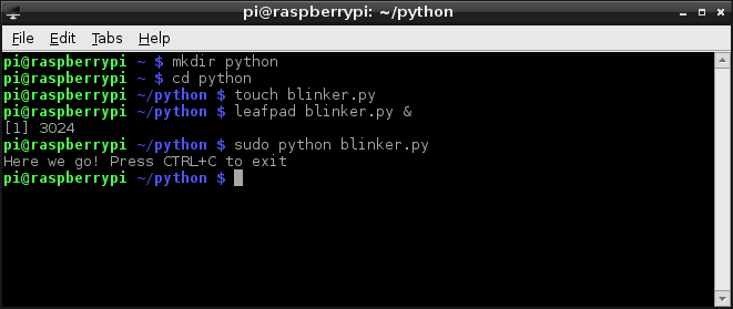
To begin, we need to create a Python file. You can do this through the GUI-based file explorer. Or, if you want a terminal-based solution, open up LXTerminal, and navigate to a folder you’d like the file to live (or create one). And create a new folder with these commands:
pi@raspberrypi ~/code $ mkdir python
pi@raspberrypi ~/code $ cd python
Create a file – we’ll call ours “blinker” – and terminate it with a .py extension. Then open it up in your favorite text editor. Nano works, as does Pi’s default GUI text editor, Leafpad.
pi@raspberrypi ~/code/python $ touch blinker.py
pi@raspberrypi ~/code/python $ leafpad blinker.py &
That’ll open up a blank text file (the “&” will open it in the background, leaving the terminal in place for future use). Time for some code!
2. Codify
Here’s an example sketch that incorporates everything we learned on the last page. It does a little input and output, and even handles some PWM. This assumes you’ve set up the circuit as arranged on the Hardware Setup page.
COPY CODE
# External module imports import RPi.GPIO as GPIO import time # Pin Definitons: pwmPin = 18 # Broadcom pin 18 (P1 pin 12) ledPin = 23 # Broadcom pin 23 (P1 pin 16) butPin = 17 # Broadcom pin 17 (P1 pin 11) dc = 95 # duty cycle (0-100) for PWM pin # Pin Setup: GPIO.setmode(GPIO.BCM) # Broadcom pin-numbering scheme GPIO.setup(ledPin, GPIO.OUT) # LED pin set as output GPIO.setup(pwmPin, GPIO.OUT) # PWM pin set as output pwm = GPIO.PWM(pwmPin, 50) # Initialize PWM on pwmPin 100Hz frequency GPIO.setup(butPin, GPIO.IN, pull_up_down=GPIO.PUD_UP)# Button pin set as input w/ pull-up # Initial state for LEDs: GPIO.output(ledPin, GPIO.LOW) pwm.start(dc) print("Here we go! Press CTRL+C to exit") try: while 1: if GPIO.input(butPin): # button is released pwm.ChangeDutyCycle(dc) GPIO.output(ledPin, GPIO.LOW) else: # button is pressed: pwm.ChangeDutyCycle(100-dc) GPIO.output(ledPin, GPIO.HIGH) time.sleep(0.075) GPIO.output(ledPin, GPIO.LOW) time.sleep(0.075) except KeyboardInterrupt: # If CTRL+C is pressed, exit cleanly: pwm.stop() # stop PWM GPIO.cleanup() # cleanup all GPIO
# External module imports
import RPi.GPIO as GPIO
import time
# Pin Definitons:
pwmPin = 18 # Broadcom pin 18 (P1 pin 12)
ledPin = 23 # Broadcom pin 23 (P1 pin 16)
butPin = 17 # Broadcom pin 17 (P1 pin 11)
dc = 95 # duty cycle (0-100) for PWM pin
# Pin Setup:
GPIO.setmode(GPIO.BCM) # Broadcom pin-numbering scheme
GPIO.setup(ledPin, GPIO.OUT) # LED pin set as output
GPIO.setup(pwmPin, GPIO.OUT) # PWM pin set as output
pwm = GPIO.PWM(pwmPin, 50)  # Initialize PWM on pwmPin 100Hz frequency
GPIO.setup(butPin, GPIO.IN, pull_up_down=GPIO.PUD_UP) # Button pin set as input w/ pull-up
# Initial state for LEDs:
GPIO.output(ledPin, GPIO.LOW)
pwm.start(dc)
print("Here we go! Press CTRL+C to exit")
try:
while 1:
if GPIO.input(butPin): # button is released
pwm.ChangeDutyCycle(dc)
GPIO.output(ledPin, GPIO.LOW)
else: # button is pressed:
pwm.ChangeDutyCycle(100-dc)
GPIO.output(ledPin, GPIO.HIGH)
time.sleep(0.075)
GPIO.output(ledPin, GPIO.LOW)
time.sleep(0.075)
except KeyboardInterrupt: # If CTRL+C is pressed, exit cleanly:
pwm.stop() # stop PWM
GPIO.cleanup() # cleanup all GPIO
After you’ve typed all of that in (don’t forget your whitespace!) save.
Running the Script
The RPi.GPIO module requires administrator privileges, so you’ll need to tag a sudo on to the front of your Python script call. To run your “blinker.py” script, type:
pi@raspberrypi ~/code/python $ sudo python blinker.py
With the code running, press the button to turn on the digital LED. The PWM-ing LED will invert its brightness when you press the button as well.
Press CTRL+C to cleanly exit the script.